The Protolis guide to compression molding
In this guide, you will find comprehensive instructions for Compression Molding, a widely used method for crafting precise, high-quality rubber components.
Technical support for compression molding
• Best design practices for compression molding
Achieving success in compression molding requires careful attention to both design and process efficiency. As with any manufacturing method, there is a constant need to strike a balance between product quality and cost-effectiveness. Well-optimized designs improve manufacturability while reducing material waste, minimizing tooling complexity, and shortening production cycles. By following established best practices, manufacturers can ensure that compression-molded parts meet performance requirements while remaining economically viable.
5 best practices for compression-molded parts
Effective design for manufacturability (DFM) ensures that compression-molded parts are not only easier to produce but also cost-effective and efficient in terms of production speed. Here are five best practices to consider when designing for compression molding:
Optimize wall thickness
Design parts with moderate wall thickness (1.3–25 mm or 0.051–0.98 inches) to balance material usage and cooling times. Thinner walls use less material and cool faster, reducing overall production costs.
Minimize undercuts
While compression molding can accommodate recessed features, designs should decrease undercuts to ensure optimal molding. Undercuts may necessitate complex ejection mechanisms, such as sliders, which increase tooling expenses.
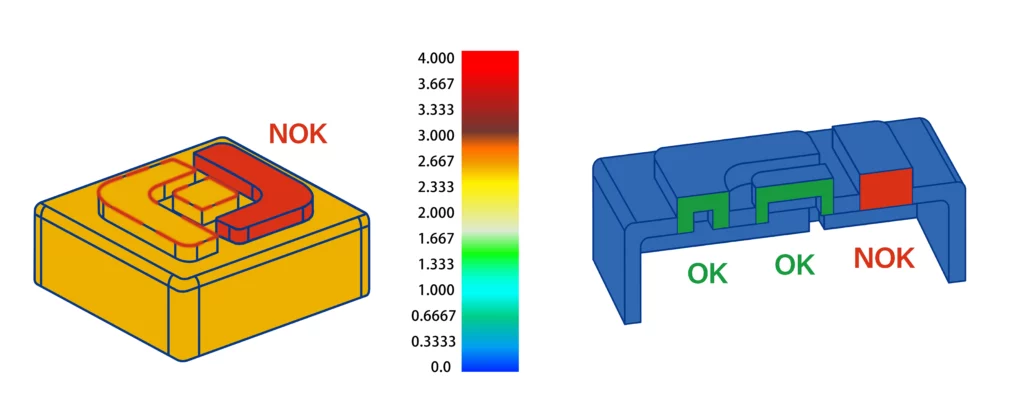
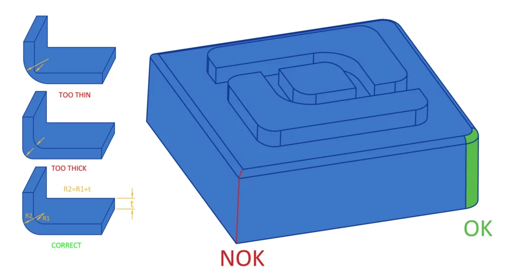
Smooth transitions
Avoid sharp corners and abrupt changes in wall thickness to ensure smooth material flow and uniform cooling, maintaining the structural integrity and esthetic quality of the part.
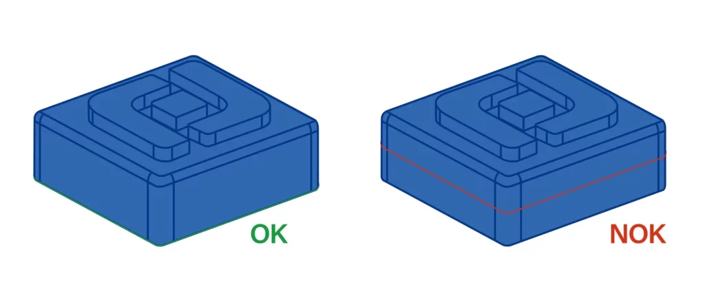
Strategic parting line placement
Place parting lines thoughtfully to minimize their visibility, particularly in flash molds. Consider the impact of witness lines and flashes on the part’s appearance, even if it is not a cosmetic part.
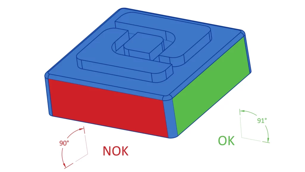
Utilize suitable draft angles
Incorporate draft angles that are proper for easy part removal from the mold, thereby reducing the risk of damage during ejection and improving the efficiency of the molding process.
At Protolis, we extend DFM guidance to our clients, ensuring their designs are optimized for compression molding. Our expertise helps refine product designs to enhance manufacturability, driving down costs and speeding up time-to-market for all compression-molded parts.
• Understanding rubber compression molding tolerances
Navigating the tolerances in rubber compression molding is essential for achieving the desired product quality. The Association for Rubber Products Manufacturers (ARPM) classifies these tolerances into four tiers, from high precision to basic levels, facilitating appropriate selection based on product requirements:
- A1 – High Precision: This is the most stringent tolerance level, used for applications requiring high precision. It necessitates the use of costly molds, fewer cavities per mold, and rigorous inspection and control measures.
- A2 – Precision: This level is less stringent than A1, yet it still ensures a high level of precision. It requires detailed inspection, though the methods are less complex than those needed for A1.
- A3 – Commercial: This tolerance is commonly used for commercial products, where standard precision is sufficient for functionality and performance.
- A4 – Basic: The least strict tier, A4, is used where some dimensional control is necessary, but cost constraints are significant.
Tolerances are categorized further into fixed and closed dimensions.
- Fixed dimensions are those that remain constant, machined into the top or bottom of the mold (without a parting line).
- Closed dimensions are formed when the mold halves meet (with a parting line).
Tolerance tables for imperial (in) and metric (mm)
| Nominal Dimension (in) | A1 Fixed | A1 Closure | A2 Fixed | A2 Closure | A3 Fixed | A3 Closure | A4 Fixed | A4 Closure |
| 0–0.4 | 0.004 | 0.005 | 0.006 | 0.008 | 0.008 | 0.013 | 0.013 | 0.032 |
| 0.4–0.63 | 0.005 | 0.006 | 0.008 | 0.010 | 0.010 | 0.016 | 0.016 | 0.036 |
| 0.63–1 | 0.006 | 0.006 | 0.010 | 0.013 | 0.013 | 0.020 | 0.020 | 0.040 |
| 1–1.6 | 0.008 | 0.010 | 0.013 | 0.016 | 0.016 | 0.025 | 0.025 | 0.045 |
| 1.6–2.5 | 0.010 | 0.013 | 0.016 | 0.020 | 0.020 | 0.032 | 0.032 | 0.050 |
| 2.5–4 | 0.013 | 0.016 | 0.020 | 0.025 | 0.025 | 0.040 | 0.040 | 0.056 |
| 4–6.3 | 0.016 | 0.020 | 0.025 | 0.032 | 0.032 | 0.050 | 0.050 | 0.063 |
| 6.3–over | x .004 | x .005 | x .005 | x .008 | x .008 | x .010 |
| Nominal Dimensions (mm) | A1 Fixed | A1 Closure | A2 Fixed | A2 Closure | A3 Fixed | A3 Closure | A4 Fixed | A4 Closure |
| 0–10 | 0.1 | 0.13 | 0.16 | 0.2 | 0.2 | 0.32 | 0.32 | 0.8 |
| 10–16 | 0.13 | 0.16 | 0.2 | 0.25 | 0.25 | 0.4 | 0.4 | 0.9 |
| 16–25 | 0.16 | 0.2 | 0.2 | 0.32 | 0.32 | 0.5 | 0.5 | 1 |
| 25–40 | 0.2 | 0.25 | 0.32 | 0.4 | 0.4 | 0.63 | 0.63 | 1.12 |
| 40–63 | 0.25 | 0.32 | 0.4 | 0.5 | 0.5 | 0.8 | 0.8 | 1.25 |
| 63–100 | 0.32 | 0.4 | 0.5 | 0.63 | 0.63 | 1 | 1.1 | 1.4 |
| 100–160 | 0.4 | 0.5 | 0.63 | 0.8 | 0.8 | 1.25 | 1.25 | 1.6 |
| 160–over | x .004 | x .005 | x .005 | x .005 | x .008 | x .010 |
Selecting the right tolerance tier is crucial for striking a balance between product performance, manufacturing efficiency, and cost. At Protolis, we can meet all these tolerance levels with extreme precision, ensuring high-quality products tailored to our clients’ specific needs.
• Possible finishes for compression-molded rubber parts
The surface finish of compression-molded rubber and silicone parts is crucial for their performance and longevity.
Factors influencing surface finishing
- Mold surface quality: The mold’s surface quality is crucial as it directly impacts the finish of the molded part. Different standards, such as SPI (Society of Plastics Industry) and VDI (Verein Deutscher Ingenieure), are used to specify the degree of polish.
- SPI finishes range from A1 (high gloss) to D3 (rough textured), with varying degrees of smoothness achieved through different polishing methods, such as diamond buffing for high gloss and dry blasting for rough textures.
- VDI finishes, on the other hand, use a numeric scale (e.g., VDI 12 to VDI 45), indicating the roughness from stone polishing to dry blasting.
- Rubber type: The type of rubber used affects the texture and quality of the surface finish. Different rubbers respond differently to the finishing process, with some achieving smoother finishes than others. For instance, natural rubber can achieve very smooth finishes, while synthetic rubbers might require specific conditions for optimal results.
- Amount of mold release agent: The quantity and type of mold release agent used can affect the surface finish. Too much agent can lead to a duller finish, while too little might cause the rubber to stick to the mold, making it difficult to achieve a smooth finish. Silicone-based agents are generally preferred for their effectiveness and minimal impact on the finish.
- Deflashing: The method used to remove excess material, or flash, from a molded part also affects the surface finish. Techniques like trimming or grinding must be carefully controlled to avoid surface damage, which can compromise the appearance and functionality of the part.
Each of these factors must be carefully managed to ensure that the molded rubber parts meet the required specifications for functionality and appearance. Selecting the right combination of mold quality, rubber type, release agent, and flash removal technique is crucial for achieving the desired outcome.
Surface finish classifications for compression-molded rubber parts
The Association for Rubber Products Manufacturers (ARPM) classifies surface finishes into four categories:
- F1: This is the highest quality finish, providing a smooth, polished surface without imperfections. It is achieved using highly polished steel molds. The tightest tolerances are applied to critical dimensions, and visual defects, such as parting lines, flow marks, and flash, are almost entirely eliminated.
- F2: It allows for minimal, unpolished tool marks. It offers a polished finish but is less meticulous than F1. Some visible parting lines and slight flashing might be present, but they do not affect part functionality. Commonly used in automotive seals, gaskets, and industrial components where a clean appearance and reliable performance are important, but not at the same stringent level as Class F1.
- F3: Known as a “commercial finish,” larger parting lines, flash, and minor surface imperfections are allowed if they do not compromise the performance or function of the part. Suitable for commercial applications where the primary concern is functionality rather than esthetics, such as rubber mounts, bushings, and gaskets used in non-visible areas.
- F4: Lowest quality finish where cosmetic appearance is not a priority. Significant flash, parting lines, and surface irregularities are permissible if they do not affect the part’s performance.
Generally, F3 is sufficient for many applications unless a smoother surface is critical for the product’s function or appearance. Choosing a finer finish like F1 or F2 will increase mold costs due to the higher level of precision required in the mold’s surface.
Possible surface finishing methods
Here are several finishing methods for compression-molded rubber parts, each tailored to enhance the properties and performance of the final product:
- Fluorination: This process involves exposing the rubber part to a fluorine gas mixture to modify its surface properties. This modification makes the rubber more resistant to weather, temperature, and certain chemicals, like solvents. The alteration is only surface-deep, preserving the core properties of the material.
- Low-friction coating: Various coatings are applied to reduce friction and enhance wear resistance. The coatings can be selectively applied to specific areas, enhancing flexibility in manufacturing.
- Flocking: This technique utilizes man-made fibers, which are aligned electrostatically on an adhesive layer. Flocked surfaces reduce friction, noise, and dirt accumulation while also improving moisture regulation, sealing, and electrical insulation. Flocking can be applied partially by masking non-target areas during the adhesive application.
Each of these methods is selected based on the specific requirements of the application. At Protolis, we offer a range of finishing options for our rubber compression-molded parts. Our primary focus is on improving the functionality, appearance, and performance of our rubber components.
Explore all the finishing options available at Protolis.
• Cost optimization for compression molding
Various factors affect the cost of compression molding projects. Understanding these factors is vital to managing expenses, so let us take a closer look.
Continue your exploration of compression molding in other chapters:
How does compression molding work?
Benefits and limitations of compression molding
When to choose compression molding for prototypes and low volume manufacturing?